LDPM
Lattice Discrete Particle Model
LDPM is a novel analytical approach for modeling the response of heterogeneous and granular materials, such as composite laminates, ceramics, concrete, gravels, and soils. The premise of the LDPM formulation is that most materials are not homogenous when considered at a sufficiently small dimensional scale (micro- and meso-scale). This heterogeneous character has a paramount relevance for the description of strain localization, crack initiation, and crack propagation, which, in turn, strongly influence the ultimate failure mode of a structural system. Continuum-based models, which homogenize material behavior, are inherently incapable of capturing the mesoscale interactions and as such become complex and inadequate in the failure range.
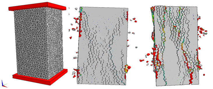
Unconfined compression test
A prism specimen of concrete is placed between two rigid platens. Unconfined compression test is simulated to capture the failure modes in two different situations: high/low friction between specimen and platens. Different failure modes are expected as follows.
Mixed mode fracture
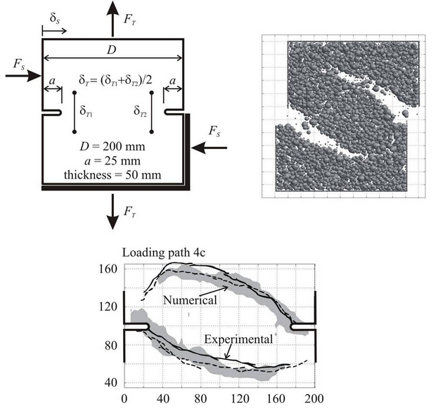
This figure depicts the setup of the mixed-mode fracture test in which a double notched prismatic panel was loaded in tension (T) and shear (S). The shear load was applied first up to a shear force close to the force capacity; then the tension was applied under displacement control keeping the shear load constant. The numerical simulation shows the typical curved cracks propagating from the notch tips towards the opposite side of the specimens.
Biaxial test of concrete
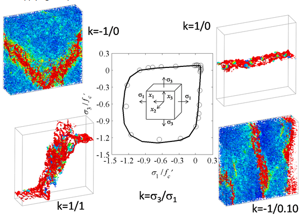
In this figure the results of biaxial quasi-static tests on plain concrete panels are reported. In the center of the picture one can see the comparison between the numerical (solid curves) and experimental (circles) failure domains normalized with the compressive strength. The top left of the figure shows classical shear band failure characterizing uniaxial unconfined compression tests. The top right shows the failure mode under uniaxial tension. The bottom left is relevant to equi-biaxial tension characterized by a 45 deg fracture. The bottom right reports the failure mode obtained while applying compression in the vertical direction and transverse tension.
Tension tests on fiber reinforced concrete
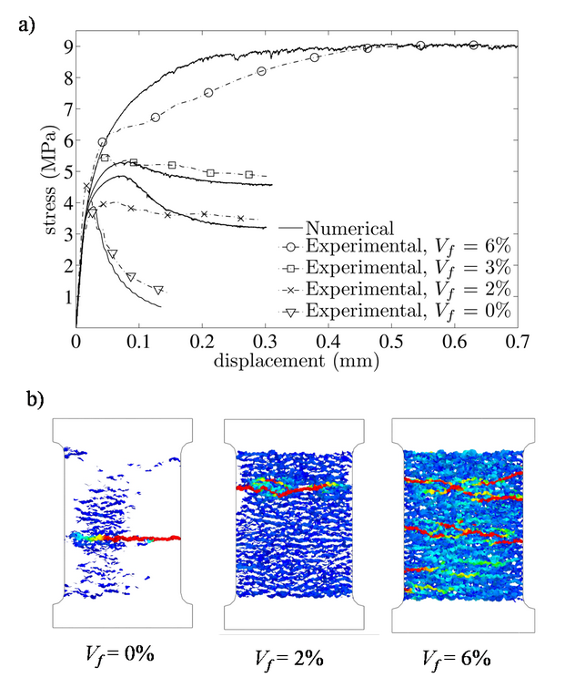
This post discusses the numerical simulations of tension testes on fiber reinforced concrete specimens. Figure (a) below shows experimental and numerical stress versus displacement curves for four different fiber volume fractions (Vf ): 0% (plain concrete), 2%, 3%, and 6%. The lattice discrete particle model is able to predict the increased strength and ductility due to the effect of fibers. The behavior gradually transitions from softening for plain concrete and low Vf , to hardening for high Vf . The numerical results are further investigated in Fig. (b), where contours of the mesoscale crack opening at the end of the simulations are reported for three fiber volume fractions. For plain concrete, the crack pattern is characterized by one localized crack that propagates from one side of the specimen towards the other. As fracture propagates, material outsidethe crack unloads as the overall load applied tothe specimen tends to zero. For the 2% Vf , there is still one main crack propagation, but the entire specimen features diffuse cracking and no unloading occurs. Absence of unloading outside the main crack is due to the fact that even though the overall behavior is softening, the stress versus displacement curve shows a non-zero residual stress associated with the fiber crack bridging effect. Finally, for the 6% Vf , the crack pattern is characterized by several branched cracks whose propagation is arrested by the effect of the fibers. No unloading occurs outside the main cracks since the overall behavior is strain-hardening and, up to a displacement of 0.5 mm (average nominal strain of 0.5 mm / 120 mm = 0.42%), no reduction of the load carrying capacity can be observed.
Fracture of fiber reinforced concrete
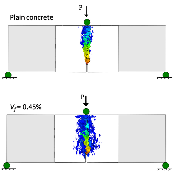
This post deals the results of three-point bending test simulations on notched specimens. Only the central part of the specimen is simulated through the accurate lattice discrete particle model while the two lateral parts are modeled used elastic finite elements. This is reasonable because the presence of the notch ensures that damage localizes ahead of the notch tip. The figures below the meso-scale crack openings (blue=0.0005 mm, red=0.66 mm and above) for plain concrete (top) and fiber reinforced concrete (bottom) with a 0.45% volume fraction. As one can see for the fiber reinforced case fracture are less localized compared to the plain concrete case.
